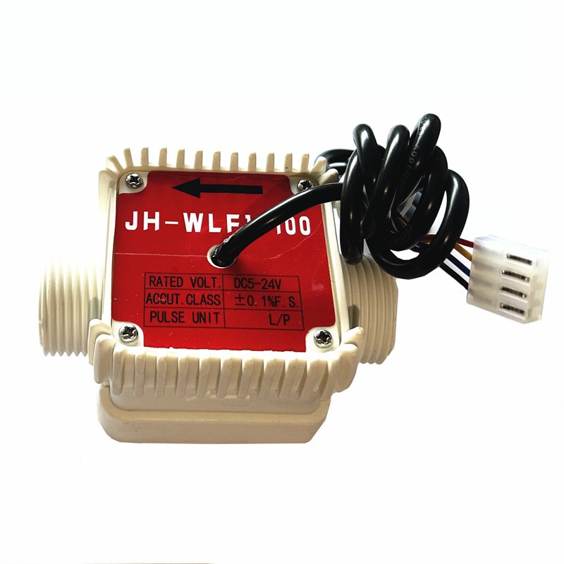
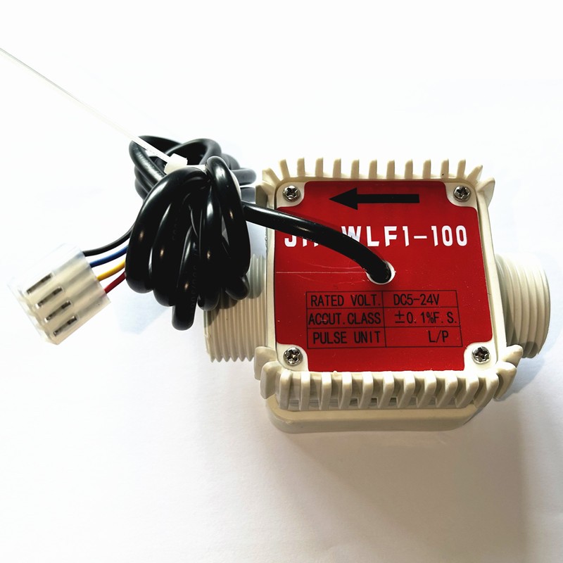
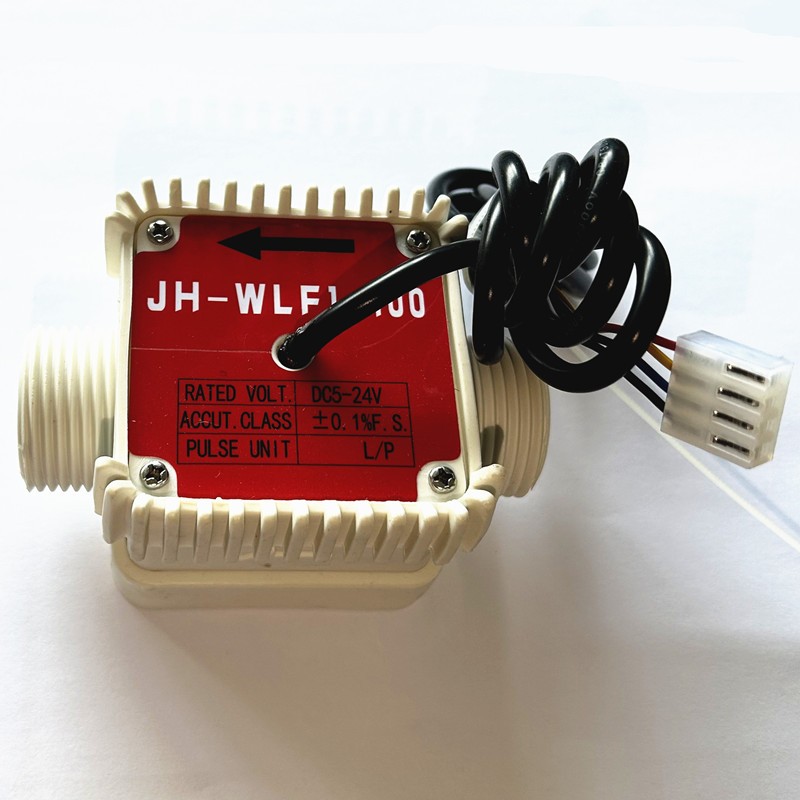
WLF1 Flow meter Impeller-Hall sensor Measuring device
I. Product Overview
This advanced flowmeter stands out in the market by leveraging the impeller - Hall sensor non - contact measurement technology. The innovation behind this technology lies in its ability to offer highly accurate and reliable flow measurements. When the medium, whether it's a liquid or a gas, makes its way through the pipeline, it imparts sufficient kinetic energy to drive the impeller into rotation.
The impeller is not just a simple mechanical component; it is equipped with a magnetic element. As the impeller spins, this magnetic element passes by the Hall sensor at regular intervals. The Hall sensor, which operates based on the Hall effect, is extremely sensitive to changes in the magnetic field. Each time the magnetic element on the impeller passes by, it triggers the Hall sensor, causing it to generate a pulse signal. A remarkable characteristic of this signal is that its frequency is precisely proportional to the flow rate of the medium. This linear relationship between the signal frequency and the flow rate forms the basis for accurate flow measurement.
One of the notable design features of this flowmeter is the absence of physical buttons. In today's era of digital connectivity, this design choice simplifies the device's structure and reduces the risk of mechanical failures associated with buttons. Instead, the flowmeter is designed to directly transmit the collected data to an external device through a cable. This external device can be a programmable logic controller (PLC), a counter, or an Internet of Things (IoT) terminal, allowing for real - time data monitoring and analysis.
This flowmeter has a wide range of applications, especially in flow monitoring scenarios involving substances like urea and diesel. In the automotive industry, for example, accurate urea flow monitoring is crucial for the proper functioning of selective catalytic reduction (SCR) systems, which help reduce nitrogen oxide emissions. Similarly, in the fuel industry, precise diesel flow measurement is essential for inventory management and fuel dispensing operations.
II. Working Principle
The working principle of this flowmeter is a fascinating interplay of mechanical and electrical processes. The flow of the medium through the pipeline acts as the driving force for the impeller. As the medium moves, it exerts a force on the impeller blades, causing the impeller to rotate. The speed at which the impeller rotates is linearly related to the flow rate of the medium. This linear relationship is a result of the well - designed aerodynamics and hydrodynamics of the impeller.
The impeller blades are embedded with permanent magnets, typically made of high - strength materials such as neodymium magnets. These magnets are carefully positioned on the impeller blades to ensure that as the impeller rotates, they create a periodic change in the magnetic field around the Hall sensor. The Hall sensor, which is fixed on the outside of the impeller, is constantly monitoring the magnetic field. When the magnetic field changes due to the rotation of the impeller and the movement of the magnets, the Hall sensor converts this magnetic change into an electrical pulse.
The generated pulse signal then embarks on a journey through the cable. It is transmitted to a receiving device, such as a PLC, counter, or IoT terminal. Once the signal reaches the receiving device, it undergoes a series of calculations. These calculations are designed to convert the pulse signal into real - time flow rate data and accumulated flow data. Real - time flow rate data provides information about the current flow speed of the medium, while accumulated flow data gives the total volume of the medium that has passed through the flowmeter over a certain period.
III. Technical Parameters
1. Model
The flowmeter is identified by the model JH - WLF1 - 100. This model number serves as a unique identifier for the specific design and features of this flowmeter. It helps in product identification, inventory management, and technical support.
2. Size
The flowmeter has a size specification of G 1”. This size is a common standard in the industry, which ensures compatibility with a wide range of pipelines and connection fittings. The standard size makes it easier for users to integrate the flowmeter into their existing systems without the need for extensive modifications.
3. Flow Range
The flow range of this flowmeter is from 10 to 100 L/min. This range is carefully calibrated to meet the requirements of various applications. For applications with low - flow requirements, such as laboratory experiments or small - scale industrial processes, the lower end of the flow range can provide accurate measurements. On the other hand, for applications with higher flow rates, such as large - scale fuel dispensing or industrial fluid transfer, the upper end of the flow range ensures reliable performance.
4. Working Pressure
The flowmeter is designed to operate at a working pressure of 0.3Mpa. This working pressure specification takes into account the structural integrity of the flowmeter and the performance of its internal components. It ensures that the flowmeter can function properly under normal operating conditions without being damaged by excessive pressure.
5. Span Error
The span error of the flowmeter is ≤3%. Span error refers to the deviation between the measured value and the actual value over the entire flow range. A span error of ≤3% indicates a high level of accuracy in flow measurement. This low error rate is crucial for applications where precise flow control and measurement are required, such as in chemical processing or pharmaceutical manufacturing.
6. Repeatability
The repeatability of the flowmeter is ≤3%. Repeatability measures the ability of the flowmeter to provide consistent measurement results when the same flow rate is measured multiple times under the same conditions. A repeatability of ≤3% ensures that the flowmeter can deliver reliable and consistent performance over time, which is essential for maintaining the quality and efficiency of industrial processes.
IV. Installation and Commissioning Key Points
1. Impeller Protection
Before installing the flowmeter, it is of utmost importance to ensure the cleanliness of the pipeline. Welding slag or particulate matter in the pipeline can pose a serious threat to the proper functioning of the impeller. These foreign objects can get stuck between the impeller blades, causing the impeller to jam. A jammed impeller will lead to inaccurate flow measurements or even complete failure of the flowmeter.
To prevent such issues, if the medium contains impurities, a filter of ≥80 mesh should be installed at the front end of the flowmeter. The filter acts as a barrier, capturing large particles and preventing them from entering the flowmeter. The 80 - mesh specification ensures that the filter can effectively trap most of the impurities while allowing the medium to flow through smoothly.
The flowmeter is available in different material options. It can be made of aluminum alloy (L), stainless steel (B), or plastic (F). The choice of material depends on various factors, such as the nature of the medium, the operating environment, and cost considerations. Aluminum alloy offers a good balance between strength and weight, stainless steel provides excellent corrosion resistance, and plastic is suitable for applications where cost - effectiveness and chemical resistance are priorities. The number 1 in the model indicates external thread, while an empty space implies internal thread. This threading specification is important for proper connection to the pipeline.
2. Sensor Calibration
When the flowmeter is powered on for the first time, it is essential to perform sensor calibration. In the empty pipe state, the impeller should be stationary, and the output pulse should be 0. This is the baseline condition for calibration. By ensuring that the output pulse is 0 when there is no flow, we can establish a reference point for accurate measurement.
To further verify the proper functioning of the sensor, we can gently blow the impeller to make it rotate manually. While the impeller is rotating, we need to check whether there is a pulse voltage change on the signal line. A normal functioning sensor should generate a corresponding pulse voltage change as the impeller rotates. This manual calibration step helps to identify any potential issues with the sensor, such as a faulty connection or a malfunctioning Hall sensor.
3. Magnetic Field Interference Protection
The Hall sensor is highly sensitive to magnetic fields. External magnetic fields, especially those generated by power cables, can interfere with the normal operation of the Hall sensor. To mitigate this interference, the distance between the Hall sensor and the power cable should be ≥30cm. This physical separation helps to reduce the influence of the magnetic field generated by the power cable on the Hall sensor.
Alternatively, a metal sleeve can be used for shielding. A metal sleeve acts as a Faraday cage, which can effectively block external magnetic fields from reaching the Hall sensor. By using a metal sleeve, we can ensure that the Hall sensor operates in a relatively stable magnetic environment, thereby improving the accuracy and reliability of the flowmeter.
Wenzhou Jiahao Petroleum Machinery Co., Ltd. is the manufacturer of this high - quality flowmeter. With its expertise in the field of petroleum machinery, the company ensures that the flowmeter meets the highest standards of quality and performance.


