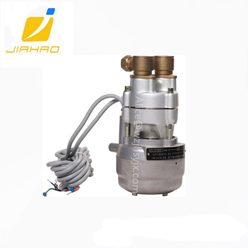
Vapor Recovery Vacuum Pump for Fuel Dispenser
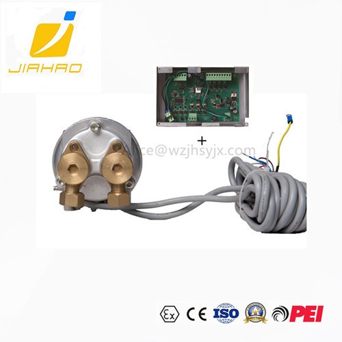
Control part parameters
Supply voltage: 230VAC ± 15%
Input current: 0.5 A
power: 110 W
Output voltage: 36 VDC ± 15%
Output current: 3.5 A
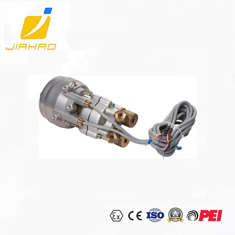
1.4.2 Variable Frequency Vacuum Pump Parameters:
Input voltage:36 VDC ± 15%
Power frequency:50/60Hz
DC frequency conversion power: 45 W
Speed: 0-1500 r/min
Rated discharge:45 L/MIN
Maximum flow rate:60 L/MIN
Per turn displacement:37mL
Exterior dimensions of pumps:358(long)×230(wide)×178(high)
Extreme pressure:≤-0.06 MPa
Pre pressure:≤150mbar
Ex-mark:Ex d IIB T4 Gb
Shell protection grade:IP55
1.5 Working and environmental conditions
Ambient temperature:-40℃~60℃;
Relative humidity:10%~90%;
Atmospheric pressure:86kPa~106kPa。
Working medium: oil-gas mixture
Scope of application: 1 zone and 2 zone sites containing explosive gas mixtures of Class II A and Class II B, T1 - T4 groups;
1.6 Product description
1.6.1 Scope of application
This product is designed to be used with a device or in a machine, and can only be used in the machine of the manufacturer with which it cooperates, but also to ensure that the corresponding safety operation requirements are met.
The model JH-NP-80 of the oil and gas recovery pump must be used in the oil and gas recovery equipment of the gas station to absorb the mixture of oil and gas.
Be careful!
Combustible gases or liquids produced in operation belong to explosion-proof grade IIA, and the standard classification spacing is more than 0.9mm. The oil and gas recovery pump must have electrostatic grounding device.
Fire retardant caps (including components) must be manually inspected, especially for pollution and corrosion. If necessary, they should be cleaned up at appropriate intervals. Their surrounding environment and inlet temperature should not exceed 60 C.
The atmospheric temperature of the outlet pipeline should not exceed 95 +5.
Operating pressure of outlet pipeline should not exceed 0.015 MPa compared with atmospheric pressure. When oil and gas recovery pumps are used in protective systems, the following conditions must be observed:
The maximum length of hose between distribution valve and oil and gas recovery pump is less than 10 m m in inner diameter of oil and gas recovery hose and less than 6 m in coaxial hose.
A) The diameter of the outer circle of the coaxial hose is less than 38 m m and the length is less than 6 m.The length of DN15 (G1/2) hose is less than 3 m.
B) In addition, one of the following containers shall be installed on the same line as the rear pipe.
Before pumping, the installation distance of that container must be between 0.3 m and 2.5 m, and the minimum length between hoses must be 0.5 m.
Be careful!
Other applications, especially the transport of mixtures, the possibility of explosion, and other applications beyond those described above are not permitted, and may cause serious personal and property damage.
1.6.2 Function description
The pump works on the principle of eccentric gear, that is, the output shaft of the motor is connected by pins to drive the gear to rotate. The gear rotates in a circle to complete a cycle. The mixture of oil and gas is sucked into the intake valve through the flame arrester and compressed in the cylinder. The compressed mixture of oil and gas is blocked by the intake valve or the outlet valve, thus being discharged through the flame arrester cap at the gas end.
2.Transportation, storage, initial operation
2.1 Transport and storage
This product is transported in a special lined carton. In this way, damage in transportation can be prevented. If necessary, the product should be packaged in the original package.
During the transportation of products, the vertical position should be maintained.
During the transportation and storage of products, special measures should be taken to prevent the products from being damped and affected by extreme temperature.
The product can only be transported at low pressure, and the gas in the cavity and hose can be discharged.
The product must be assembled immediately after delivery. Products kept in the original packaging can be stored in a warm and dry dustproof room. If the product is to be stored for a long time, for example, as an alternative product, it must be free from dust and moisture.
2.2 Transport and storage requirements
Temperature:-40 ℃~60 ℃;
Humidity:10%~90%(No condensation droplets)
2.3 Assembly Suggestions and Initialization Operations
This product is designed to be assembled in components. It can only be installed by engineers who are professionally trained and familiar with potential hazards. Only when all relevant safety requirements are met can the product operate.
2.3.1 environment condition
Care should be taken to select the place where the product is installed to facilitate operation, cleaning and maintenance. In particular, connectors and operating components are more accessible.
If the product is fixed in the machine or housing, it must be note


